In high-speed electronics manufacturing, choosing the right resistance welding machine for connector assembly is critical to eliminating the bottlenecks of traditional soldering. As connectors shrink and performance demands rise for AI servers, automotive I/O modules, and high-frequency telecommunications, manufacturers require precise, reliable, and scalable micro-welding solutions. This comprehensive guide explores how to select the ideal resistance welding system to optimize signal integrity, mechanical strength, and production efficiency.
What Is a Resistance Welding Machine for Connector Assembly?
A resistance welding machine for connector assembly is a high-precision manufacturing system engineered to join fine wires, high-speed twinaxial (twinax) cables, or micro-coaxial lines directly to connector terminals and paddle cards. Unlike standard welding systems used in heavy industries, connector resistance welding operates at a micro-scale. It utilizes localized heat and mechanical force to create solid-state or fusion bonds between delicate materials. Because the process does not introduce foreign solder alloys, the resulting joint maintains the pure conductivity and low impedance of the base metals, which is critical for high-frequency, high-bandwidth signal transmission.
Modern resistance welding machines integrate advanced electronic control systems to regulate the welding energy with extreme precision. High-performance systems utilize pulse heating technology, where the output voltage, pulse width, and welding pressure are tightly controlled via closed-loop feedback systems. Built-in current sensors and advanced pressure sensing mechanisms monitor the physical characteristics of each joint in real time. This ensures that electrical current is discharged only under the exact structural conditions required, preventing micro-scale defects.
These machines are highly specialized for handling delicate workpieces without causing thermal degradation to surrounding plastics, liquid crystal polymer (LCP) connector housings, or cable insulation. A top-tier system can directly weld ultra-fine enameled wires, micro-coaxial conductors, and precision terminals with diameters or thicknesses ranging from 0.02 mm to 0.30 mm. This capability makes them indispensable for mass-producing high-density interconnects, including high-speed I/O interfaces, backplane connectors, and next-generation automotive sensor terminals.
Which Connector and Cable Components Can Be Resistance Welded?
Resistance welding is incredibly versatile, but it truly shines when applied to high-frequency and high-density components that cannot tolerate the prolonged thermal exposure of conventional soldering. In modern electronics, this process is widely applied to join copper, brass, bronze, and silver-plated alloy wires directly to gold- or tin-plated connector terminals. Because the welding heat is concentrated strictly at the contact interface for a fraction of a second, the surrounding insulation and plastic housings remain completely undamaged.
The most common components and assemblies that benefit from this technology include:
- High-Speed Cable Assemblies (DACs): Direct Attach Copper (DAC) cables, including 400G/800G/1.6T OSFP, QSFP-DD, SFP-DD, and PCIe Gen 5/6 twinax cable assemblies. Direct welding of the conductors to the PCB paddle card ensures minimal insertion loss and return loss.
- Precision Stamped Terminals & Micro-Interconnects: Fine-pitch board-to-board connectors, flexible printed circuit (FPC) connectors, micro-pin headers, and high-density terminal blocks where mechanical space is extremely constrained.
- Automotive Harnesses and Sensors: High-vibration I/O connectors, automotive radar/LiDAR sensor terminals, and heavy-duty wire-to-terminal connections that require superior thermal and mechanical stability under harsh operating conditions.
By utilizing direct metal-to-metal bonding, manufacturers eliminate the added weight, bulk, and electrical resistance of solder alloys. This results in highly reliable, low-impedance connections that meet the stringent signal integrity standards of AI data centers and automotive safety systems.
How Resistance Welding Works in Connector Production
The fundamental physics of resistance welding relies on Joule’s Law, which states that the heat generated is directly proportional to the square of the welding current, the electrical resistance of the contact interface, and the duration of the current flow. In connector assembly, the machine's electrodes clamp the cable conductor and the connector terminal together under a precise mechanical force. This clamping action stabilizes the contact resistance at the joint interface and ensures a consistent electrical path.
Once the pre-set clamping force is reached, the machine's controller releases a high-current, low-voltage electrical pulse through the electrodes. Because the contact resistance between the wire and the terminal is significantly higher than the resistance of the electrodes themselves, localized heat is instantly generated at the interface. This heat softens or melts the adjacent metals, while the continuous force of the electrodes squeezes the materials together to form a solid-state weld nugget.
The entire process takes place in a matter of milliseconds. This ultra-fast cycle time is the secret to protecting heat-sensitive connector housings. The heat is generated and dissipated so quickly that it does not have time to travel down the wire to melt the insulation or warp the plastic connector body. The result is a clean, highly conductive joint with a minimal heat-affected zone (HAZ), preserving the precise physical geometry required to maintain characteristic impedance.
Key Parameters That Affect Welding Quality
Achieving consistent weld quality in high-speed connector production requires precise control over several interconnected physical parameters:
- Welding Current and Voltage Amplitude: For micro-connector assembly, the pulse amplitude must be adjustable in micro-steps—often with a resolution as fine as 0.01 V within a 0.01 V to 1.99 V range. If the voltage is slightly too low, the joint will suffer from weak adhesion; if it is too high, it will cause material expulsion, sparking, or severe deformation of the terminal.
- Welding Pulse Width (Duration): This determines how long the electrical energy is applied to the joint. In fine-wire and twinax applications, this is measured in milliseconds, typically ranging from 0 to 29.9 ms with a resolution of 0.1 ms. Because different plating materials (such as gold, tin, or nickel) have varying thermal conductivities and melting points, the pulse width must be customized to ensure the plating is displaced or melted without burning the underlying base metal.
- Electrode Force (Pressure): Proper mechanical pressure is essential to break through surface oxides, flatten microscopic surface roughness, and prevent air gaps that cause electrical arcing. Advanced resistance welding machines utilize high-precision pressure sensors to ensure that the electrical pulse is only triggered when the mechanical force is within the targeted window. Consistent force throughout the weld cycle prevents splashing and guarantees a uniform weld thickness.
How to Choose the Right Resistance Welding Machine
When evaluating a resistance welding machine for connector assembly, your first step must be analyzing your wire and material specifications. If your production involves ultra-fine coaxial cables (down to 44 AWG) or twinaxial cables that require direct welding to paddle cards, you need a specialized fine-wire welding machine. Ensure the system features high-precision energy regulation and pulse heating capabilities to handle delicate copper alloys without causing wire burn-through.
Next, assess the power and control requirements of your production environment. A reliable machine should offer a stable power supply and a robust maximum output pulse power to ensure it can handle various material thicknesses. Look for a controller that offers closed-loop feedback, enabling real-time adjustments to voltage and current fluctuations to keep the energy output perfectly consistent from the first weld to the millionth.
To help you evaluate your equipment needs, the table below outlines the standard technical specifications for a high-performance, semi-automatic single-station resistance welding system designed for precision connectors and high-speed cables:
| Equipment Specification | Parameter Details |
|---|---|
| Maximum Output Pulse Power | 540 VA |
| Welding Pulse Width | 0–29.9 ms (resolution 0.1 ms) |
| Main Pulse Amplitude | 0.01–1.99 V (resolution 0.01 V) |
| Weldable Wire/Conductor Diameter | Ø 0.02–0.30 mm |
| Control Mode | Manual / Automatic |
| Welding Station Dimensions | 90 x 90 mm |
| Heating Method | Pulse heating |
| Power Supply | AC 220 V |
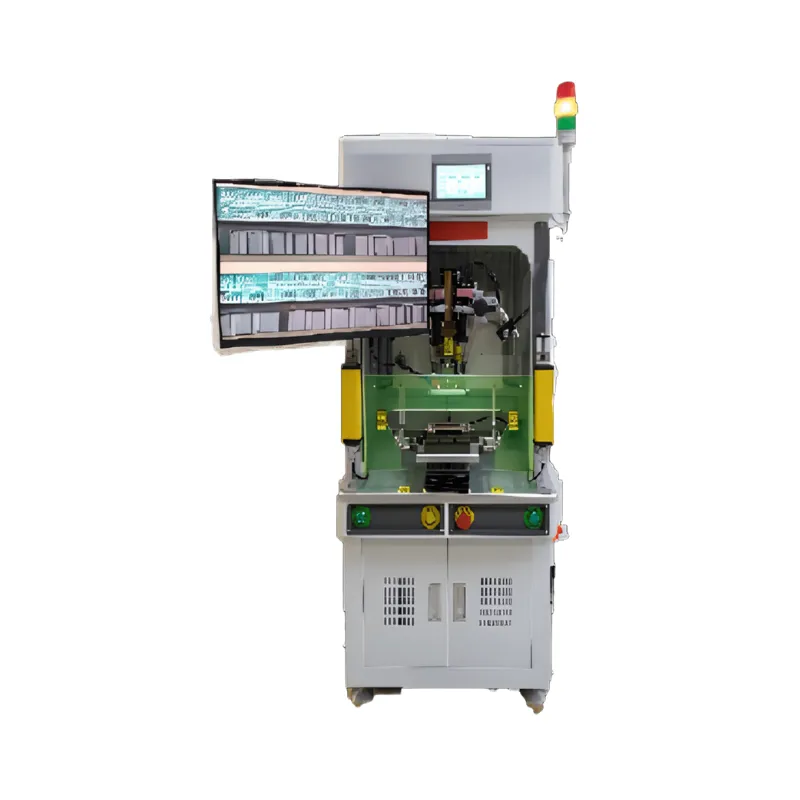
| Equipment Dimensions | L 620 × W 600 × H 1,600 mm (excluding monitor) |
Finally, consider the physical footprint and scalability of the equipment. If you are running a flexible production floor, a floor-type standalone design is highly advantageous. This allows you to deploy the machine as a manual workstation initially and later integrate the exact same welding module into an automated, multi-station production line when your volume scales up.
Manual, Semi-automatic, and Fully Automatic Welding Solutions
Selecting the right level of automation depends on your production volume, product mix, and labor costs.
Manual Welding Stations
Manual welding stations are highly effective for R&D laboratories, prototyping, and low-volume, high-mix connector assembly. They allow operators to manually position complex wire configurations under a microscope, making them ideal for highly customized or low-run assemblies where automated tooling would be cost-prohibitive.
Semi-Automatic Solutions
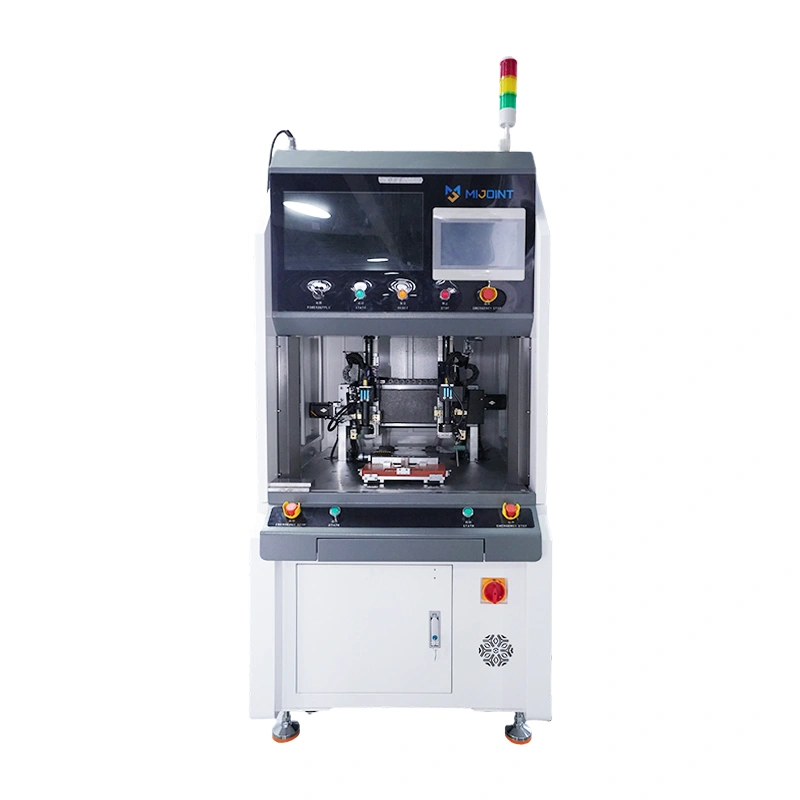
For growing production lines, semi-automatic solutions—such as a single-station resistance welding machine—offer an exceptional balance of cost and efficiency. These systems feature a compact floor-type design with a dedicated welding station (for example, a 90 x 90 mm station). The operator manually loads the connector and wire into a fixture, and the machine automatically handles the clamping, pressure sensing, precise pulse heating, and real-time current monitoring, significantly reducing human error.
The typical workflow for a semi-automatic station follows this sequence:
Manual Loading → Precise Sensor Clamping → Pulse Heating Weld → Automated Quality Check
Fully Automatic Assembly Lines
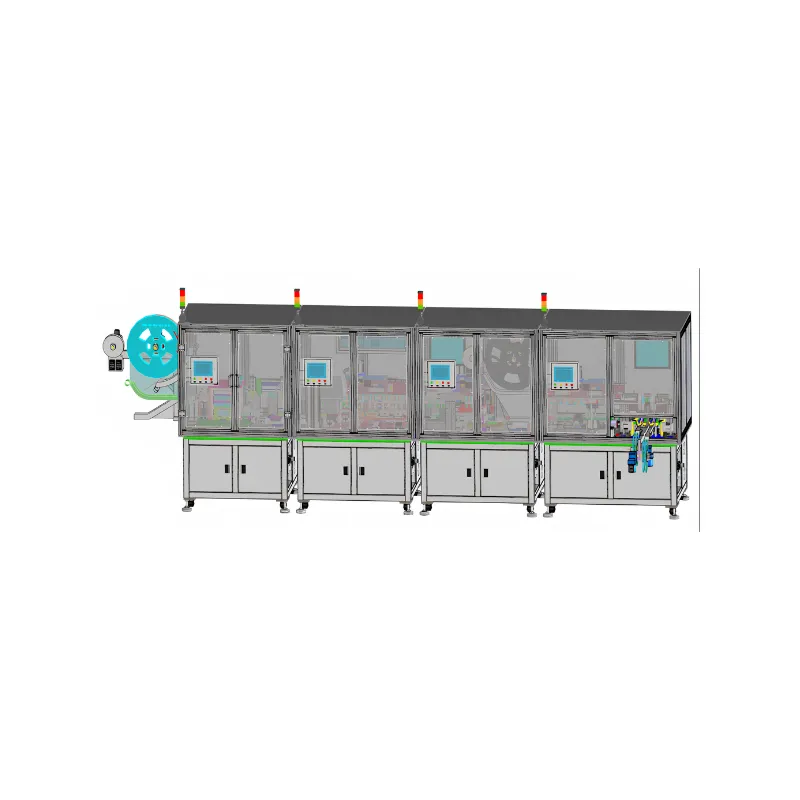
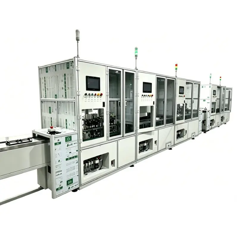
For high-volume, next-generation interconnect manufacturing (such as OSFP or CDFP cable assemblies), fully automatic assembly lines are the gold standard. These advanced systems integrate multiple complex processes into a single continuous flow. They feed raw materials, perform laser stripping, execute vision-guided alignment, carry out high-precision resistance welding, perform 100% automated optical inspection (AOI), and package the finished products. This level of automation minimizes human intervention, drives cycle times down to 0.8 to 1.0 seconds per unit, and ensures flawless repeatability.
Comparison of Automation Levels
To help you determine the best fit for your manufacturing facility, the table below compares the key characteristics of manual, semi-automatic, and fully automatic resistance welding solutions for connectors and high-speed cables:
| Feature / Metric | Manual Welding Stations | Semi-Automatic Solutions | Fully Automatic Assembly Lines |
|---|---|---|---|
| Production Volume | Low (R&D, prototyping, small batches) | Medium to high (scaling production lines) | Ultra-high volume (mass production) |
| Average Cycle Time | Slow (highly dependent on operator skill) | Moderate (consistent machine-controlled cycles) | Ultra-fast (0.8 to 1.0 seconds per unit) |
| Operator Involvement | High (manual positioning, clamping, and firing) | Moderate (manual loading and unloading of fixtures) | Minimal (unattended operation, automated material feeding) |
| Quality Consistency | Variable (operator-dependent) | High (automated clamping and pulse parameters) | Extremely High (vision guidance and 100% AOI) |
| Traceability | Limited (manual logging) | Good (real-time current monitoring and sensors) | Complete (full MES integration, individual joint data) |
| Initial Investment | Low | Moderate | High |
| Best-Fit Applications | Custom high-speed cable prototypes, low-volume aerospace connectors | Automotive sensor terminals, precision I/O connectors, mid-volume terminal blocks | 800G/1.6T OSFP, QSFP-DD, PCIe Gen 5/6 DAC twinax cable assemblies |
Common Welding Defects and Solutions
Even with high-quality machinery, process drift can occasionally introduce defects if parameters are not monitored. The table below outlines the most common defects in connector welding, their root causes, and recommended solutions:
| Common Defect | Root Cause | Recommended Solution |
|---|---|---|
| Virtual Welding / Weak Joints | Low heat input or insufficient electrode pressure. | Increase pulse width or adjust electrode force to break surface oxides. |
| Burn-through / Wire Breakage | Excessive energy density or misaligned electrode tips. | Lower pulse amplitude in 0.01 V steps; inspect and realign electrode tips. |
| Sparking / Material Splashing | Contaminated electrode tips or premature current discharge. | Clean electrodes regularly; verify pressure sensor threshold before firing. |
Virtual Welding or Weak Joints
This is a common issue where the cable conductor and connector terminal appear bonded but separate under minimal mechanical stress. This is usually caused by insufficient heat input or low electrode pressure that fails to break through surface oxides on the plated terminal. The solution is to slightly increase the pulse width or adjust the electrode force to stabilize the contact resistance.
Burn-through or Wire Breakage
This occurs frequently when working with ultra-fine twinax or micro-coaxial wires under 0.1 mm. This happens when the energy density is too high or the electrode tips are misaligned, concentrating the heat in a tiny area. To resolve this, you must lower the main pulse amplitude using fine-resolution adjustments (such as 0.01 V steps) and inspect the electrode tips for wear or misalignment.
Sparking or Material Splashing
This defect can damage delicate connector components, melt adjacent plastic housings, and contaminate the welding area. This is typically triggered by discharging the current before the electrodes have fully clamped the workpiece, or by oxidized electrode tips. Implementing a machine with a built-in pressure sensor prevents the system from firing prematurely, while establishing a regular electrode cleaning and dressing protocol keeps the contact surfaces pristine.
Welding Inspection and Quality Traceability
In critical industries like automotive manufacturing and AI server infrastructure, a single failed connector joint can lead to catastrophic system downtime or signal degradation. Therefore, relying on post-weld destructive testing is no longer sufficient. High-performance resistance welding systems incorporate real-time electrical monitoring via built-in current and voltage sensors. These sensors capture the dynamic energy curve of every single weld, comparing it against a pre-programmed "golden profile" and instantly flagging any deviations.
To complement electrical monitoring, high-speed production lines integrate automated vision inspection systems. Utilizing high-resolution 2D or 3D cameras, these systems inspect the physical geometry of the weld joint immediately after the cycle. They verify the correct wire placement on the terminal or paddle card, check for excess deformation, and measure the weld height to ensure the joint meets strict dimensional tolerances before the part moves to the next station.
To achieve true smart manufacturing, these inspection tools must be linked directly to your Manufacturing Execution System (MES). By integrating the welding machine’s sensor data and vision inspection results with the MES, you establish a complete, data-driven quality traceability loop. Every high-speed connector produced is assigned a unique tracking profile containing its exact welding voltage, pulse duration, pressure curve, and visual inspection images, giving your customers complete confidence in your product's reliability and signal integrity.
Why Choose Mijoint for Connector Resistance Welding Automation
When it comes to high-precision connector assembly, Mijoint stands out as a world-leading strategic automation partner. Founded in 2018 in Dongguan’s Songshan Lake, Mijoint specializes in customized automation solutions for high-speed cables, connectors, and 2D/3D vision inspection. Our deep engineering expertise in resistance welding, laser welding, and high-precision assembly allows us to serve global leaders in AI servers, data centers, automotive manufacturing, and industrial automation.
Choosing Mijoint means partnering with an elite R&D powerhouse. Our team consists of over 200 dedicated engineers—42% of whom hold Senior Engineer titles—led by industry veterans with an average of 15 years of experience. We offer cutting-edge technology that achieves Apple-grade assembly precision of up to 0.01 mm and ultra-fast cycle times of 0.8 to 1.0 seconds per unit. Our semi-automatic single-station resistance welding machines are engineered with advanced pressure sensing, built-in current sensors, and high-precision energy regulation to guarantee flawless conductivity and mechanical strength.
At Mijoint, we understand that manufacturing speed and uptime are critical to your bottom line. Operating out of a 45,000 m² state-of-the-art facility, we can deliver duplicate production lines within 45 days and custom-developed lines within 75 days. Furthermore, our global service network spans Malaysia, Vietnam, Thailand, and Mexico, backed by a strict Service Level Agreement: a 30-minute remote response guarantee, 2-hour technician dispatch, and 24-hour on-site technician arrival to keep your production running smoothly.
Conclusion
Selecting the right resistance welding machine is a critical decision that directly impacts the electrical performance, mechanical integrity, and overall throughput of your connector assembly line. By carefully evaluating your wire diameters, material plating, and power requirements, you can select a system that provides the exact energy control and mechanical stability your process demands.
Moving away from manual soldering to precision resistance welding not only eliminates common defects like cold joints and thermal damage but also future-proofs your production capabilities. Whether you require a flexible, semi-automatic standalone machine for precision terminals or a fully integrated, high-speed automated assembly line for 800G OSFP/QSFP-DD twinax cables, partnering with an industry leader like Mijoint ensures that your manufacturing process remains highly efficient, precise, and fully traceable.