Introduction
In modern high-speed manufacturing, relying on manual labor for complex assemblies is a recipe for operational bottlenecks, quality drift, and escalating costs. As production demands intensify across high-tech sectors like AI servers, datacenters, and automotive telematics, factories face the relentless challenge of maintaining extreme precision at high throughput. This is especially true for high-frequency, high-bandwidth components such as high-speed cables, advanced connectors, FAKRA RF modules, and optical communication transceivers.
To overcome these physical limitations, forward-thinking manufacturers are transitioning from rigid, manual setups to custom assembly automation equipment. These tailored systems are engineered to handle complex, high-precision tasks that standard, off-the-shelf machines simply cannot execute, transforming the manufacturing floor into a highly optimized, scalable ecosystem.
What Is Custom Assembly Automation Equipment?
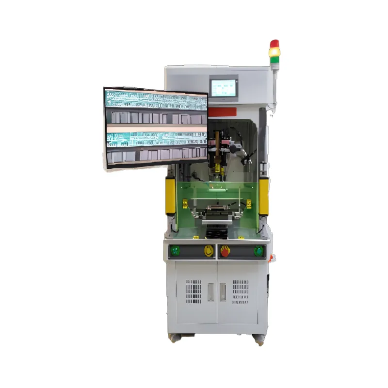
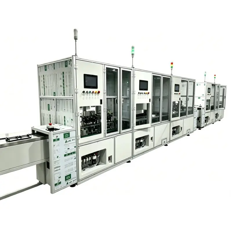
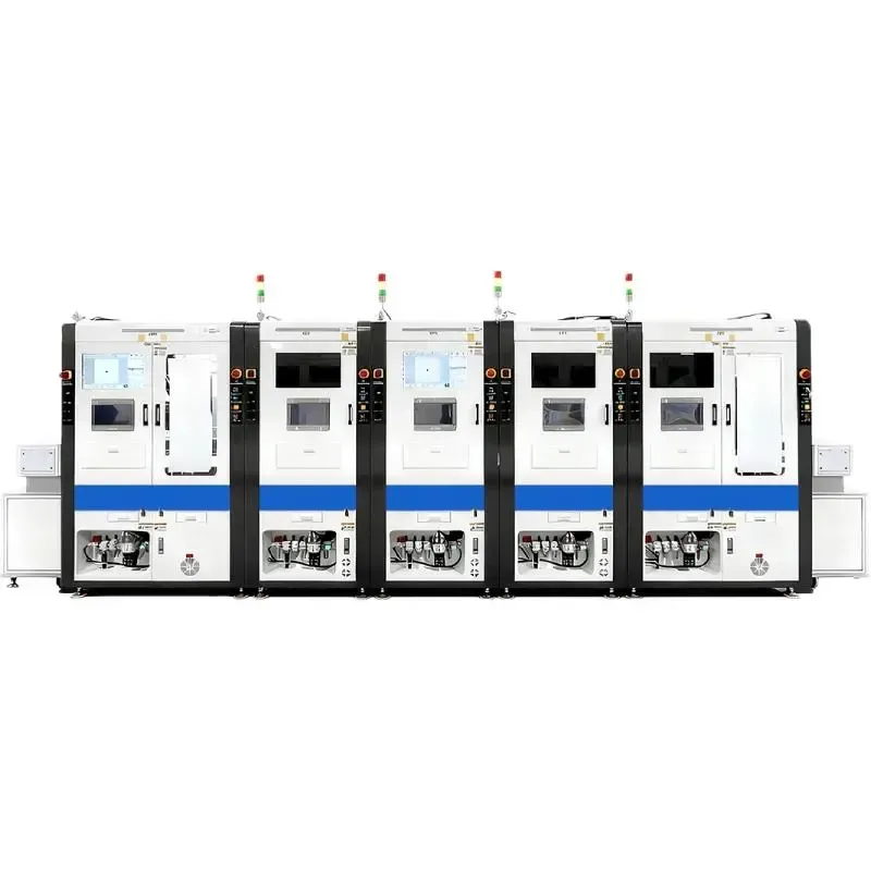
Custom assembly automation equipment refers to bespoke machinery engineered from the ground up to automate specific manufacturing, assembly, and testing processes. Unlike standard catalog machines, custom systems are tailored to a specific product’s geometry, material properties, and high-frequency performance requirements. They integrate advanced technologies like high-precision vision systems, active optical alignment, laser welding, and robotic handling.
These systems leverage modular architectures and advanced motion control to perform highly repetitive, high-precision operations. For example, Mijoint designs solutions that achieve Apple-grade assembly precision of up to 0.01 mm and rapid cycle times of 0.8 to 1.0 seconds. This level of customization pushes the boundaries of physical production limits, enabling the damage-free handling of fragile optical fibers and ultra-fine coaxial cables.
When Does a Factory Need a Custom Assembly Solution?
Many factory managers struggle to identify the exact tipping point for investing in custom assembly automation equipment. The clearest indicator is when manual labor or standard machinery can no longer meet strict quality tolerances, resulting in high scrap rates or low First Pass Yield (FPY).
In high-frequency sectors, manual assembly often introduces human error that degrades signal integrity. If your production line suffers from frequent defects during intricate steps—such as micro-soldering of high-speed cable wires, precise crimping of FAKRA terminals, or multi-channel optical fiber alignment—manual processes are no longer viable.
Another critical trigger is the need to scale production rapidly while keeping labor costs in check. When labor shortages disrupt your schedule, or when a product’s cycle time requirements drop below the threshold of human capability, custom automation becomes a strategic necessity.
What Information Is Required Before Automation Design?
Designing a highly efficient custom automation system requires a deep dive into your product’s physical characteristics, high-frequency performance metrics, and production goals. Engineers must analyze your current production volumes, target cycle times, and space constraints on the factory floor.
For specialized components like high-speed cables and optical transceivers, the design input must also include:
- Mechanical Tolerances: Exact dimensions of terminals, housings, and optical sub-assemblies.
- Material Properties: Cable flexibility, insulation sensitivity, and optical fiber bend radii.
- Testing Standards: Insertion loss (IL), return loss (RL), and voltage standing wave ratio (VSWR) specifications.
- Infrastructure Standards: Electrical, pneumatic, and safety standards to ensure seamless integration.
Providing comprehensive data up front prevents costly design revisions and ensures the final custom assembly automation equipment aligns perfectly with your facility's infrastructure.
From Product Samples and Drawings to Process Planning
The engineering journey begins with your 2D and 3D CAD drawings, alongside physical product samples. Automation experts use this data to perform a rigorous Design for Manufacturing (DFM) analysis, identifying potential assembly bottlenecks and suggesting minor product modifications that can drastically simplify automation.
During process planning, engineers map out the optimal sequence of operations. For high-speed interconnects, this involves detailing steps like outer jacket stripping, shielding foil folding, inner core sorting, laser welding, and housing insertion. This stage utilizes Design of Experiments (DOE) validation to test critical variables—such as laser power for wire welding or force profiles for FAKRA terminal crimping—ensuring that every step of the assembly is mathematically sound and physically repeatable before a single piece of steel is cut.
Feeding, Positioning, Assembly, Welding, Inspection, and Testing
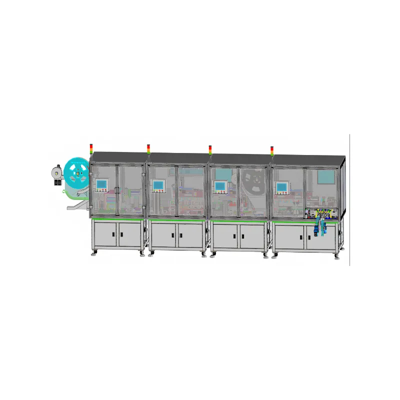
A fully integrated custom line orchestrates multiple complex processes into a single continuous workflow.
[Precision Feeding] ➔ [Vision Positioning] ➔ [Assembly & Welding] ➔ [Integrated Testing] ➔ [Traceable Unloading]- Precision Feeding: Vibratory bowls, tape-and-reel feeders, or tray denesters orient delicate parts, such as FAKRA plastic housings or optical lenses, for robotic pick-and-place systems.
- Vision-Guided Positioning: Advanced positioning fixtures, utilizing high-resolution vision assistance, align components with micron-level repeatability. This is critical for aligning optical fibers to laser diodes (TOSA/ROSA) or positioning multi-core high-speed cables.
- Assembly & Welding: Components undergo high-speed assembly. This includes precision crimping of RF connectors, UV adhesive dispensing for optical lenses, or high-speed laser welding for high-speed cable-to-PCB connections.
- Inspection & Testing: Integrated inspection systems—such as 2D/3D vision cameras or laser height differential sensors—verify dimensions and FAKRA color-code keys. Functional testing stations then perform high-frequency signal integrity, insertion loss, and return loss testing before unloading.
How Product Variations Affect Equipment Design
One of the biggest pain points in automation is handling product variations without rendering the equipment obsolete. Traditional dedicated lines struggle with product iterations, but modern custom assembly automation equipment resolves this by incorporating modular, standardized platforms.
By utilizing quick-disconnect fixtures and vision-assisted software debugging, manufacturers can achieve parallel changeovers. For example, a single custom line can assemble different FAKRA mechanical keys (A, B, C, etc.) or switch between different high-speed cable configurations (such as 8C to 16C) simply by swapping out specific functional modules and loading a new software profile. This modular design protects your capital investment and reduces long-term upgrade costs.
Key Technical Specifications for High-Speed Assembly Lines
| Parameter Item | Specification / Value |
|---|---|
| Cycle Time (CT) | 25s (High-speed cable wire preparing & welding) |
| First Pass Yield (FPY) | ≥98% |
| Overall Equipment Effectiveness (OEE) | ≥85% |
| Equipment Failure Rate | <5% |
| Mechanical Repeatability | ±0.02 mm |
| Jaw Secondary Positioning Accuracy | Y-axis ±0.01 mm, X-axis ±0.01 mm |
| Optical Alignment Resolution | Up to 0.1 μm (for silicon photonics/optical sub-assemblies) |
Cycle Time, Quality, and Traceability Requirements
In high-value industries like AI servers and automotive electronics, speed must never compromise quality. Advanced custom lines are designed to meet strict Overall Equipment Effectiveness (OEE) targets of over 85%, with First Pass Yields exceeding 98%.
Furthermore, modern compliance demands comprehensive traceability. Custom automation equipment integrates barcode scanners, RFID readers, and database logging to record the exact torque, laser power, crimping force, and high-frequency test results (like insertion loss and impedance) for every single unit produced. This ensures complete accountability and rapid troubleshooting throughout the product lifecycle.
Equipment Development, Testing, and Validation
Once the design phase is locked, the physical development of the custom assembly automation equipment begins. Highly skilled technicians precision-machine the components and assemble the mechanical, electrical, and pneumatic systems under strict quality controls.
The validation phase involves rigorous testing of the software algorithms, vision calibration, and motion control systems. For optical and RF components, testing includes verifying that the automation equipment does not introduce mechanical stress or micro-bends that could degrade signal performance. Engineers run continuous testing cycles to simulate real-world production stresses, identifying and resolving any minor bugs to guarantee the machine operates reliably at peak speeds.
Factory Acceptance Testing and Project Delivery
Before the equipment leaves the manufacturer’s facility, it must pass a rigorous Factory Acceptance Testing (FAT) protocol. During FAT, the machine is run under production-like conditions using the client's actual high-speed cables, FAKRA connectors, or optical modules to verify that cycle times, yield rates, and safety features meet all contractual specifications.
Upon successful FAT approval, the equipment is carefully dismantled, packed, and shipped to the client's facility. On-site installation, Site Acceptance Testing (SAT), and comprehensive operator training ensure a smooth handoff and a rapid ramp-up to full-scale production.
Key Sectors Driving Custom Automation
1. High-Speed Cables & Connectors
The rise of AI datacenters has driven massive demand for high-speed cable assemblies (such as DAC, ACC, and AEC) and advanced internal connectors (including NearStack, MCIO, and PCIe Gen 5/6 interfaces). Custom automation handles the delicate stripping of ultra-fine coaxial cables, precise wire sorting, laser welding to PCBs, and automated electrical performance testing, eliminating the inconsistencies of manual soldering.
2. FAKRA & Mini-FAKRA RF Connectors
Automotive ADAS, infotainment, and autonomous driving systems rely heavily on FAKRA and Mini-FAKRA connectors for high-frequency RF signals. Custom automation lines streamline the complex assembly of these multi-piece connectors—including center pin crimping, outer shield crimping, plastic housing insertion, color-key verification via vision systems, and pull-force testing.
3. Optical Communication & Silicon Photonics
Optical transceivers (from 400G to 1.6T and beyond) and Active Optical Cables (AOC) require sub-micron alignment precision. Custom automation systems integrate active optical alignment, UV curing, and laser diode welding to assemble TOSA, ROSA, and silicon photonic chips, ensuring minimal insertion loss and maximum optical coupling efficiency.
Mijoint’s Engineering and Project Delivery Process
Mijoint delivers exceptional value to global clients through a robust, four-pronged approach: leading R&D, lean project management, localized rapid service, and scalable delivery. With over 200 high-caliber engineers and a 45,000 m² state-of-the-art facility, Mijoint can deliver duplicate production lines within 45 days and fully customized lines within 75 days.
To support international operations, Mijoint provides localized rapid technical support through strategic offices in Malaysia, Vietnam, Thailand, and Mexico, backed by a strict Service Level Agreement (SLA) featuring a 30-minute remote response and 24-hour on-site arrival.
Conclusion
Investing in custom assembly automation equipment is a transformative step that directly impacts a manufacturer's bottom line. By replacing slow, error-prone manual steps with high-speed, high-precision automated workflows for high-speed cables, connectors, FAKRA, and optical communication modules, factories can dramatically increase efficiency, improve yields, and secure a competitive edge.
Partnering with an experienced, globally capable automation provider like Mijoint ensures your custom project is designed to the highest standards, delivered on time, and supported locally throughout its entire operational lifecycle.