Introduction
Solder joints are among the smallest and most critical elements in an electronic product — and among the hardest to inspect. A joint that is misaligned, incompletely bonded, or unevenly heated can pass a quick visual check and still fail in the field. For manufacturers running automated welding processes such as hot bar soldering and PGRS (pulse heated reflow soldering), the inspection question is not whether to check joints, but how to check them accurately, repeatably, and at production speed.
A solder joint inspection system provides that answer. Depending on the technology, it can verify joint geometry, detect hidden internal defects, measure solder height, or guide the welding equipment itself to align precisely with pads and conductors before the heat is ever applied. Choosing the right system requires understanding both the defect types your process produces and the capabilities and limits of each inspection technology.
This guide walks through the common pain points that drive manufacturers to invest in solder joint inspection, the defects these systems detect, the main inspection technologies available, how inspection integrates with hot bar and PGRS soldering processes, and the criteria that matter most when selecting a system. It also introduces how Mijoint's vision-guided soldering equipment builds inspection-grade positioning accuracy directly into the welding process.
What Is a Solder Joint Inspection System?
A solder joint inspection system is any combination of hardware and software that evaluates solder joints against defined quality criteria — automatically or semi-automatically — and outputs a result the production process can act on. The evaluation may happen before welding (verifying that the conductor and pad are correctly positioned), during welding (monitoring the process), or after welding (checking the finished joint).
What all solder joint inspection approaches have in common is the goal: replace subjective, fatigue-prone human judgment with repeatable measurement. A trained inspector can assess a handful of joints per minute with declining consistency over a shift; an inspection system evaluates every joint on every board, cycle after cycle, using the same criteria every time.
Importantly, inspection is not only about rejecting bad joints. The most valuable inspection data feeds back into the process itself — correcting alignment, flagging drift, and enabling welding equipment to adapt to real part variation before defects are created. This is the principle behind vision-guided soldering machines, which use 3D vision to locate pads and conductors and adjust the welding position in real time.
Pain Points: Cold Solder, Voids, and Field Returns from Welding Defects
Cold Solder Joints
A cold solder joint forms when the solder does not reach the temperature needed for proper metallurgical bonding. Visually, the joint may appear complete; electrically and mechanically, it is weak. Cold joints cause intermittent connections that pass some functional tests and fail others — one of the most frustrating failure modes in electronics manufacturing, because the defect hides inside a joint that looks acceptable. In hot bar and PGRS processes, uneven heating across the welding face is a direct cause: sections of the joint area that receive insufficient heat never fully reflow.
Voids and Internal Defects
Voids are cavities inside the solder joint — trapped gas or flux residues that reduce the effective bonding area. A joint with significant voiding may look perfect from the outside while carrying only a fraction of its intended mechanical and electrical strength. Because the defect is internal, surface-level visual checks cannot detect it, and the weakness only reveals itself under mechanical stress, thermal cycling, or vibration in the field.
Field Returns and Warranty Cost
When welding defects escape to the customer, the cost multiplies. A returned product must be diagnosed, repaired or replaced, and shipped back; in data center and automotive applications, a single failed connector can take down equipment far more valuable than the component itself. Field failures also damage customer confidence and can trigger audits or qualification reviews. Manufacturers who analyze warranty claims frequently trace a significant share of returns back to soldering processes that lacked adequate inspection coverage — which is why welding quality control deserves to be treated as a system-level investment rather than a station-level expense.
Common Solder Joint Defects and Detection Methods
Solder joint defects fall into recognizable categories, each with characteristic detection approaches:
- Misalignment and offset. The conductor sits partially or completely off its pad. Detection: position measurement before welding — vision systems that locate pads and conductors and calculate deviation — or post-weld visual comparison against the target geometry.
- Insufficient or excessive solder. Too little solder leaves a weak joint; too much creates bridges and shorts to adjacent conductors. Detection: geometry measurement of the finished joint, comparing solder area, height, or volume against specification.
- Cold joints and incomplete reflow. The solder did not fully melt and bond. Detection: surface texture and joint geometry analysis, supported by process monitoring of actual temperature and heating profile during welding.
- Voids and internal cavities. Hidden gaps inside the joint. Detection: internal inspection methods such as X-ray, which images through the joint to reveal cavities that surface inspection cannot see.
- Bridging and shorts. Solder connects conductors that should be isolated. Detection: electrical testing and visual/geometry inspection of the space between adjacent conductors.
Two practical conclusions follow from this list. First, no single detection method covers every defect type — surface geometry methods and internal imaging methods answer different questions. Second, the earlier a defect type can be detected, the cheaper it is to address: catching misalignment before welding prevents the defect entirely, while finding a void after welding means rework or scrap.
Inspection Technologies: 2D AOI, 3D SPI, and X-Ray
2D AOI (Automated Optical Inspection)
2D AOI uses cameras and image processing to examine joints from above. It verifies presence, position, and visual characteristics — solder coverage, joint outline, bridging between adjacent conductors. It is fast and well suited to high-volume checks of surface-visible features. Its limitation is depth: a 2D image cannot measure solder height or reveal anything about the joint's internal structure. A joint with acceptable appearance but hidden voiding will pass 2D AOI.
3D Inspection
3D inspection technologies reconstruct the height profile of the joint area, enabling measurement of solder height, volume, and coplanarity — features invisible in a flat image. The same 3D measurement principle also powers a different application: rather than inspecting joints after welding, 3D vision locates pads and conductors before welding and guides the equipment into correct alignment. In Mijoint's 3D vision-guided PGRS soldering machine, 3D vision positions the PCB pads and conductors, calculates position deviations in real time, and feeds the data to the main control system for adaptive alignment welding — turning inspection-grade measurement into defect prevention.
X-Ray Inspection
X-ray inspection images through the joint, revealing internal structure: voids, insufficient solder under components, and hidden bridging. It is the definitive method for internal defects that no surface technique can detect. Its trade-offs are cost and throughput — X-ray systems represent a significant investment and typically inspect samples or specific high-risk joints rather than every joint on every board. Many manufacturers use X-ray for process validation and periodic sampling while relying on faster methods for full production inspection.
Integrating Inspection with Hot Bar and PGRS Soldering
Hot bar and PGRS soldering join conductors to PCB pads using a heated bonding tool, with heat applied under controlled pressure and time. These processes demand tight alignment: the bar must contact the full welding area simultaneously, and the conductor must sit on the pad within a small positional tolerance. Two equipment-level examples show how inspection integrates with the process:
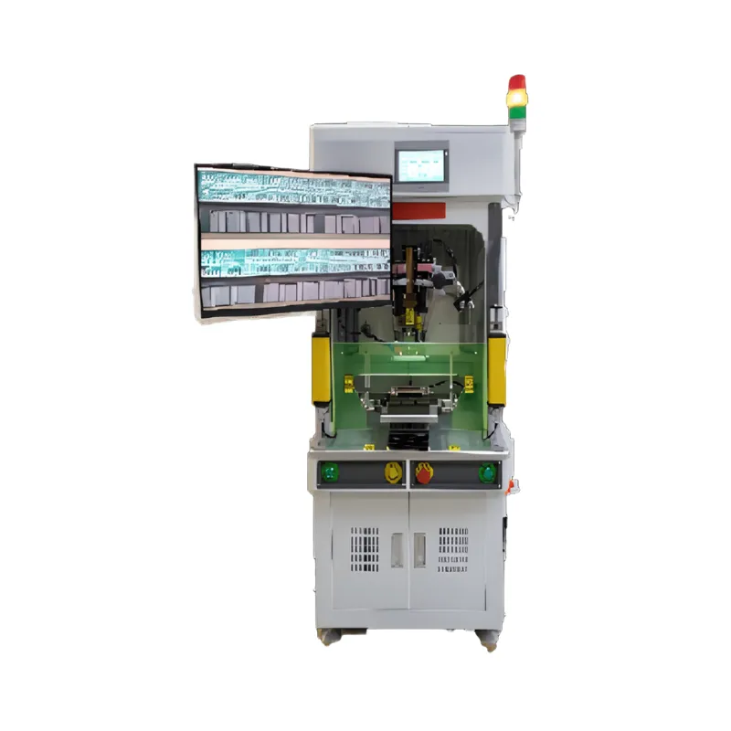
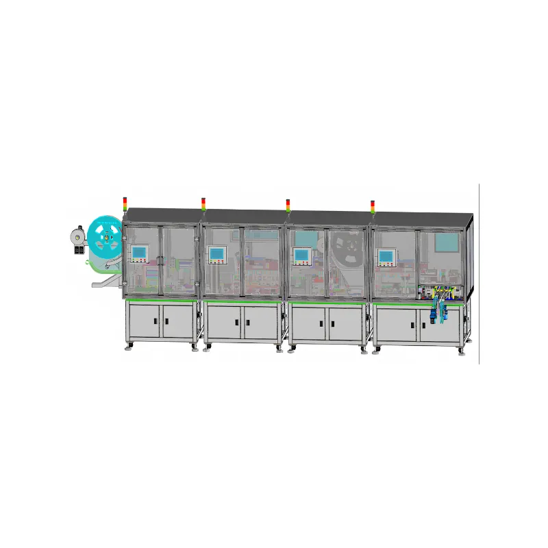
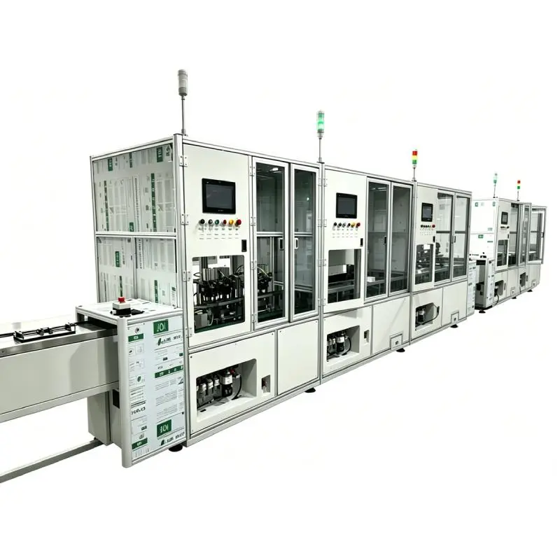
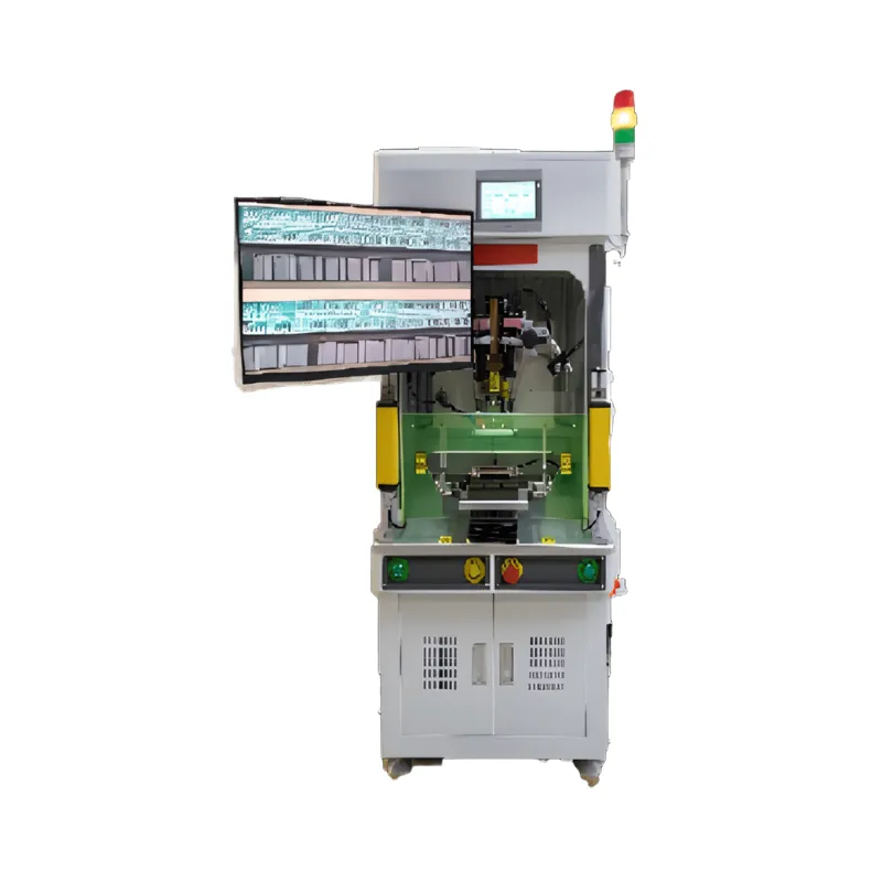
Vision-guided adaptive welding. The 3D vision-guided PGRS soldering machine (dual station) uses 3D vision to locate PCB pads and conductors, calculates position deviation in real time, and feeds the result to the main control system, which adapts the welding alignment accordingly. The dual-station design lets loading and welding overlap for throughput, and the machine supports a pre-soldering process for applications requiring pre-tinned conductors. The in-line PGRS soldering machine extends the same capability into a continuous in-line flow: automatic loading, vision recognition, conductor deviation correction, welding, and automatic unloading — vision checks are embedded in every cycle rather than performed separately downstream.
Thermal uniformity for wide welding areas. Alignment is only half of joint quality; the other half is heat. On wide welding surfaces — such as PCIE and CEM large-format circuit boards — uneven heating across the bar creates cold sections and uneven joints. Mijoint's high-power hot bar soldering machine addresses this with structural optimization and precise local resistance temperature control, achieving thermal balance across the wide welding face so the joint solders uniformly in a single operation.
Building a Closed-Loop Quality System to Eliminate Welding Issues
The most effective welding quality control is a closed loop: measurement influences the process, and the process generates new measurements. A practical closed-loop architecture for solder joint quality includes four layers:
- Pre-process verification. Before heat is applied, vision confirms that conductors and pads are present and correctly positioned. Misalignment — the cheapest defect to fix — is corrected before it becomes a joint.
- In-process adaptation and monitoring. During welding, the equipment measures real part geometry (via 3D vision deviation calculation) and adapts alignment; heating parameters are controlled and monitored so each joint receives the intended thermal profile.
- Post-process inspection. After welding, inspection appropriate to the defect risk — geometry checks for surface features, sampling X-ray for internal integrity — verifies the result before product moves downstream.
- Feedback and correction. Inspection results are analyzed for trends. A drift in joint geometry points back to feeding or alignment; a pattern of cold joints points to heating parameters. Correcting the upstream cause closes the loop and prevents defect recurrence.
Factories that implement this structure stop treating soldering defects as random events to be caught and start treating them as process signals to be eliminated. The compounding benefit is fewer field returns: joints that were welded correctly the first time, verified in-cycle, and traced through the process.
Key Selection Criteria
When comparing solder joint inspection approaches and equipment, evaluate the following:
- Defect coverage versus your actual defect profile. List the defect types your process actually produces (from yield data and returns analysis), then confirm the candidate technology detects them. A system with excellent surface coverage does not help if your losses come from internal voids.
- Integration with the welding process. Systems that measure before and during welding prevent defects; systems that only inspect afterward sort them. Vision-guided welding equipment that performs 3D deviation calculation and adaptive alignment addresses misalignment at its source.
- Speed and cycle-time impact. Inspection embedded in the machine cycle adds coverage without adding cycle time. Verify that inspection throughput matches or exceeds your line's production rate.
- Repeatability and false-call performance. Request data on measurement repeatability and false reject rates. A system that flags good joints wastes labor and erodes operator trust.
- Process capability of the welding equipment itself. Inspection cannot compensate for an unstable welding process. Evaluate the welding platform's thermal control (e.g., precise local resistance temperature control for wide welding areas) alongside its inspection features — joint quality starts with the welding equipment.
- Data connectivity. Inspection results that feed into production records support traceability and trend analysis; isolated inspection stations lose this value.
Why Choose Mijoint's Solder Joint Inspection Solutions
Mijoint integrates inspection-grade measurement directly into its soldering equipment, so joint quality is protected at the point of creation rather than checked after the fact:
- The 3D vision-guided PGRS soldering machine (dual station) locates PCB pads and conductors in 3D, calculates position deviations in real time, and feeds results to the main control system for adaptive alignment welding — with dual-station productivity and support for pre-soldering processes.
- The in-line PGRS soldering machine delivers the same 3D vision positioning and adaptive welding in a fully in-line configuration — automatic loading, vision recognition, conductor deviation correction, welding, and automatic unloading in one continuous process.
- The high-power hot bar soldering machine solves the wide-area heating challenge on PCIE and CEM large-format circuit boards, with structural optimization and precise local resistance temperature control that maintains thermal balance across the welding face for uniform, single-pass joints.
Across these platforms, the inspection capability is not a bolt-on station — it is part of the welding process itself, measuring and correcting on every cycle. If your products involve welding requirements beyond these standard configurations, Mijoint also delivers customized equipment built around your product drawings and process requirements — contact our team to request a tailored solution.
Conclusion
Choosing the right solder joint inspection system starts with your defects: map the failure modes your process actually produces, then select the technology — or combination of technologies — that detects them at the earliest possible point. Remember that 2D AOI verifies what is visible, 3D measurement adds height and enables pre-weld guidance, and X-ray reveals what is internal. Above all, give weight to inspection that is integrated into the welding process itself: vision-guided alignment, real-time deviation correction, and controlled heating prevent the majority of joint defects before they exist.
If you are evaluating welding equipment with integrated inspection capability and need a solution configured to your specific products and quality requirements, contact Mijoint's engineering team to request a customized equipment proposal. To learn more about the company's soldering capabilities and industry experience, visit the About Mijoint page.