Introduction
In modern electronics manufacturing, product dimensions keep shrinking while quality requirements keep rising. Connectors, solder joints, and dispensing patterns that were once checked by trained operators under magnifiers are now measured in fractions of a millimeter — far below what the human eye can reliably judge, cycle after cycle, shift after shift. This is why vision inspection has become a core capability of automated assembly equipment rather than an optional add-on.
Two technologies dominate the field: 2D vision inspection, which captures planar images to verify position, presence, and appearance; and 3D vision inspection, which adds height and depth data to locate surfaces and measure geometry in three dimensions. Both are widely used in automated assembly — often within the same production line — because each solves a different class of inspection problem.
This guide explains what 2D and 3D vision inspection systems are, how each technology works, the pain points they address on the factory floor, how to choose between them, and where they apply in soldering, dispensing, and component placement processes. It also shows how Mijoint integrates vision guidance directly into its automated assembly and welding equipment.
What Are 2D and 3D Vision Inspection Systems?
Vision inspection systems use industrial cameras, optics, and image-processing software to check products automatically during or after an assembly operation. Instead of relying on human judgment, the system captures an image of the part, compares it against the expected result, and outputs a pass/fail decision or positional data that the machine can act on immediately.
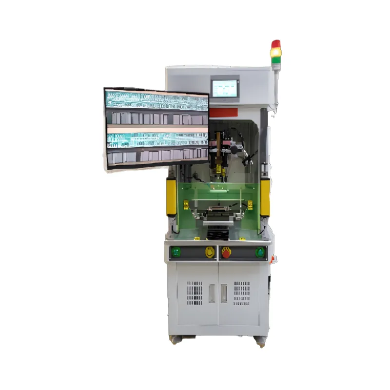
A 2D vision inspection system works with two-dimensional images. The camera sees the part from a single viewpoint, and the software analyzes features such as edges, contours, patterns, and contrasts. In automated assembly, 2D vision is most often used for position detection: locating a component on a tray, verifying that a part is present and oriented correctly, or guiding a dispensing nozzle to a known coordinate. For example, Mijoint's desktop jetting vision dispensing machine uses local vision CCD positioning to lock onto the target area before non-contact dispensing begins, ensuring the adhesive lands exactly where the process requires.
A 3D vision inspection system captures height and depth information in addition to the planar view. By reconstructing the surface profile of a workpiece, the system can locate objects in three-dimensional space — not just "where is it on the plane" but "how high is it, and at what angle." This capability is essential in processes like soldering, where the positions of PCB pads and conductors can vary slightly from piece to piece and a fixed program alone cannot guarantee accurate alignment.
Pain Points: Hidden Defects, High False Alarm Rates, and Inspection Speed Bottlenecks
Hidden Defects That Escape Manual Inspection
Many process defects are simply invisible to conventional checks. A solder joint may look acceptable from directly above while hiding insufficient bonding; a dispensing dot may be present but misplaced by a fraction of a millimeter; a conductor may sit a few tenths of a millimeter off its pad. These small deviations pass through visual spot checks, then surface later as intermittent connections, failed functional tests, or field returns. For factories shipping high-volume precision products, the cost of a defect that escapes to the customer is many times the cost of catching it at the station.
High False Alarm Rates
On the other side of the problem is the false reject. An inspection system that flags good parts as defective creates its own costs: re-inspection labor, unnecessary scrapping of usable material, and line stoppages that drain throughput. False alarms often happen when a system relies on a single detection method applied to a process with natural variation — slight brightness changes, minor part-position shifts, or surface reflections. The result is a quality system that operators learn to distrust, which undermines the entire inspection effort.
Inspection Speed Bottlenecks
Manual inspection cannot keep pace with automated production. A fully automatic assembly line completes operations in seconds per cycle; a human inspector needs far longer to examine each part, and attention degrades over a shift. When inspection becomes the slowest step, it either caps the line's output or gets skipped under production pressure. Integrating vision inspection into the automated process itself — so that every part is checked as part of the normal cycle, without adding cycle time — is the practical way to remove this bottleneck.
How 2D Vision Inspection Works
A 2D vision inspection system typically consists of an industrial CCD camera, lighting matched to the part's surface, and image-processing software. The workflow follows a consistent sequence:
- Image capture. The camera photographs the part at the inspection position. Lighting is arranged to make the features of interest — edges, marks, components — stand out clearly against the background.
- Feature recognition. The software analyzes the image to locate known features: a component outline, a fiducial mark, a dispensing target. Template matching and edge detection are common techniques for finding these features regardless of minor part-to-part variation.
- Position calculation. Once the features are found, the system calculates the exact coordinates of the target relative to the working coordinate system.
- Output and action. The result is either a judgment (pass/fail) or positional data fed to the motion system so the next operation — dispensing, welding, placement — targets the correct location.
This closed loop between seeing and acting is what separates vision-guided automation from simple snapshot inspection. In Mijoint's desktop jetting vision dispensing machine, for instance, the vision CCD first locates the dispensing target, and the jetting valve then dispenses with a minimum dot diameter of 0.3 mm and a minimum line width of 0.35 mm — precision levels that depend on accurate positioning before the adhesive is ever released.
How 3D Vision Inspection Works
3D vision inspection adds a dimension: height. Rather than treating the workpiece as a flat image, the system reconstructs its surface profile, so pads, conductors, and components are located in three-dimensional space. The process generally runs as follows:
- Profile capture. The vision system scans the workpiece and builds a 3D representation of the target area, capturing the X-Y position of features along with their height.
- Deviation calculation. The measured positions of key features — such as PCB pads and conductors — are compared in real time against the programmed nominal positions, and the deviation in each axis is calculated.
- Adaptive correction. The deviation data is fed back to the machine's main control system, which adjusts the operation parameters to compensate before the process executes.
- Process execution. The welding head, dispensing valve, or placement mechanism carries out the operation at the corrected position.
Mijoint's 3D vision-guided PGRS soldering machine (dual station) follows exactly this sequence: 3D vision locates the PCB pads and conductors, the system calculates position deviations in real time, and the results are fed back to the main controller for adaptive alignment welding. The dual-station layout allows loading and welding operations to overlap, keeping the vision system and welding head productive on every cycle. The machine also supports a pre-soldering process for applications that require pre-tinning before the final joint is made.
2D vs 3D: Which Technology to Choose?
Neither technology is universally better — they answer different questions. The right choice depends on what your process actually needs to know about the part.
Choose 2D vision when the critical information is planar: Is the component present? Is it in the right position and orientation? Is the dispensing dot where it should be? 2D systems are typically simpler to set up, faster to run, and well suited to high-speed presence checks, orientation verification, and coordinate location on flat surfaces. For dispensing applications on visible, flat target areas, a CCD-based 2D positioning system is often sufficient.
Choose 3D vision when height or geometry matters: Are the pad and the conductor at the heights the program assumes? Does the soldering target sit flush with the surface? Is there a slight tilt that a planar view would miss? 3D vision is the enabling technology for adaptive processes — operations where the machine must adjust itself to the actual part rather than assume the part is perfect. In soldering, where conductor positions can shift slightly between pieces, 3D-based deviation calculation and adaptive alignment directly protect joint quality.
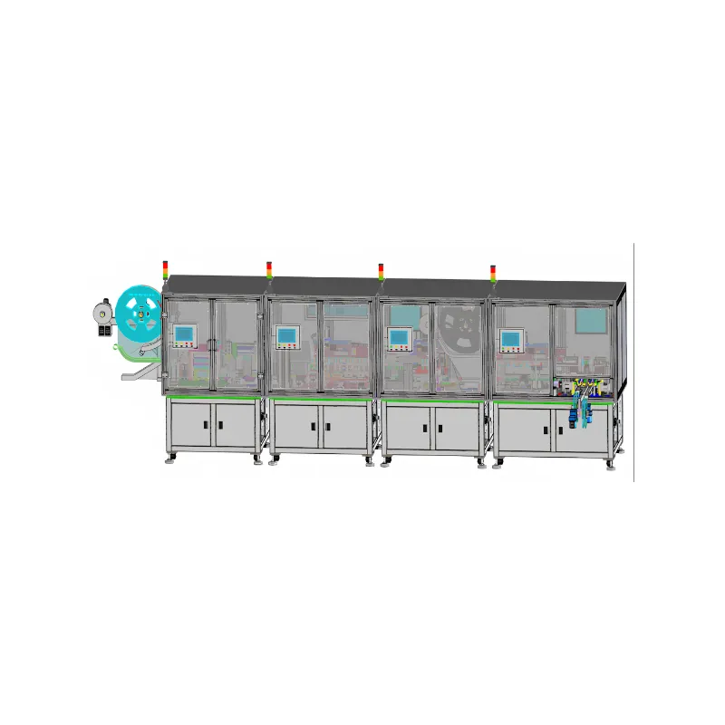
In many real lines, both are used together. A 2D check may verify feeding and orientation at the front of the line, while 3D vision guides the critical welding or dispensing step. Mijoint's in-line PGRS soldering machine illustrates the combined approach: the line performs automatic loading, vision recognition, and conductor deviation correction, then executes welding and automatic unloading — all as one continuous in-line process.
Key Applications in Soldering, Dispensing, and Component Placement
Vision-Guided Soldering
Soldering is one of the most demanding applications for vision inspection because joint quality depends on alignment accuracy between the conductor and the pad. In PGRS (pulse heated reflow soldering) processes, the welding head must press the conductor onto the pad with the correct position, force, and heat profile. The 3D vision-guided PGRS soldering machine handles this by locating pads and conductors in 3D, calculating deviations in real time, and adapting the welding position accordingly — so each joint is welded according to the actual part geometry rather than nominal coordinates. For applications requiring pre-tinned conductors, the pre-soldering process capability supports that step within the same equipment platform.
Vision-Guided Dispensing
Dispensing accuracy is limited by positioning accuracy. Adhesive dots and lines placed even slightly off-target can cause weak bonds, contamination of adjacent areas, or failed sealing. The desktop jetting vision dispensing machine addresses this with local vision CCD positioning combined with non-contact jetting technology. Because the valve never touches the workpiece, the machine can apply adhesive into tiny gaps and confined geometries where a contact-based applicator could not operate — down to a 0.3 mm minimum dot diameter and 0.35 mm minimum line width. Vision positioning ensures each dispensing cycle starts from the correct coordinates on the actual part.
Vision Inspection in Component Assembly
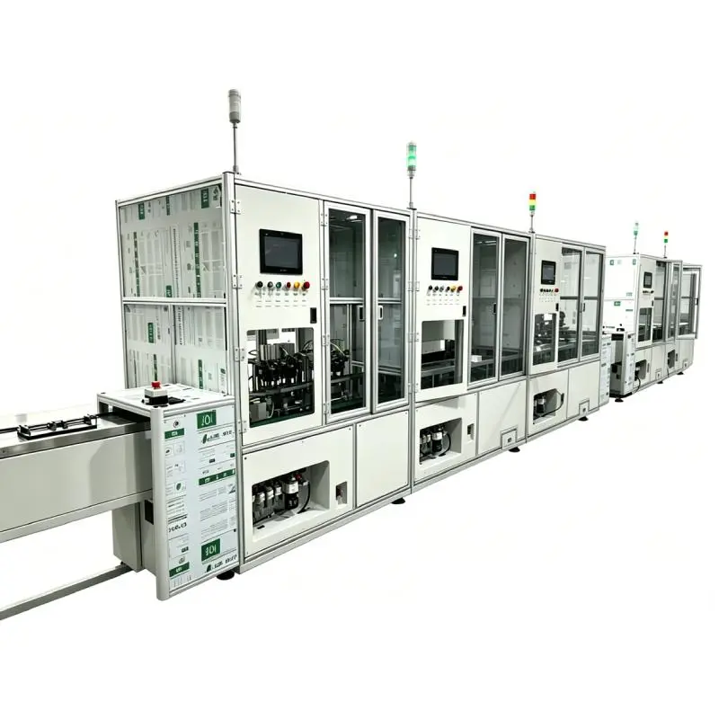
Beyond guiding processes, vision inspection also verifies assembly results. In connector assembly lines, CCD visual inspection and AOI checks confirm that components are correctly assembled before products move downstream — catching bent terminals, missing parts, or misaligned housings at the station where they were produced. On fully automatic Type-C connector assembly lines, glue detection and CCD visual checks verify intermediate process results such as adhesive presence between assembly steps. This station-level verification keeps defects from accumulating and compounding through later stages of the line.
Best Practices for Solving Vision Inspection Challenges
Based on how vision systems are integrated across modern assembly equipment, several practices consistently improve results:
- Put vision inside the process, not after it. Inspection that happens within the machine cycle — before or during welding, dispensing, and assembly — catches problems at the source and enables immediate correction, instead of discovering defects after an entire batch has been processed.
- Use vision data to adapt, not just to reject. The highest value of machine vision is not sorting good parts from bad, but allowing the equipment to compensate for real-world part variation. Real-time deviation calculation and adaptive alignment turn inspection data into process improvement on every cycle.
- Match the technology to the defect type. Use 2D vision for presence, orientation, and position checks; use 3D vision when height, coplanarity, or geometric deviation affect the process. Applying 3D where 2D suffices adds cost and complexity without benefit; relying on 2D where geometry matters leaves defects undetected.
- Standardize lighting and fixturing. Vision reliability depends on consistent image conditions. Stable part presentation and controlled illumination reduce the false alarm rate more than any software adjustment.
- Design for traceable results. When inspection results are recorded and tied to each workpiece, quality teams can analyze defect trends and trace issues back to specific processes — turning the vision system into a data source for continuous improvement.
Why Choose Mijoint's Vision-Guided Equipment
Mijoint builds vision guidance and vision inspection directly into its automated assembly and welding equipment, rather than treating them as separate bolt-on stations. The result is equipment that sees, corrects, and verifies within a single continuous process:
- The 3D vision-guided PGRS soldering machine (dual station) locates PCB pads and conductors in 3D, calculates position deviations in real time, and feeds the results to the main control system for adaptive alignment welding — with dual-station productivity and support for pre-soldering processes.
- The in-line PGRS soldering machine extends the same 3D vision positioning and PGRS welding capability into a fully in-line process: automatic loading, vision recognition, conductor deviation correction, welding, and automatic unloading in one continuous flow.
- The desktop jetting vision dispensing machine combines local vision CCD positioning with non-contact jetting dispensing, reaching a 0.3 mm minimum dot diameter and 0.35 mm minimum line width for precision applications in tight geometries.
Across Mijoint's connector assembly lines, vision inspection is likewise integrated at the process level — CCD visual inspection, AOI checks, and glue detection verify results station by station, so defects are caught where they originate. If your production involves connector types, soldering processes, or dispensing requirements beyond these standard configurations, Mijoint also delivers customized equipment built around your product drawings and process requirements — contact our team to request a tailored solution.
Conclusion
2D and 3D vision inspection are the sensory foundation of modern automated assembly. 2D vision answers the planar questions — presence, position, orientation — quickly and reliably. 3D vision answers the geometric ones — height, deviation, alignment — and enables equipment to adapt to real parts in real time. Used together, inside the machine cycle rather than after it, they address the three pain points that undermine manual and after-the-fact inspection: hidden defects, false alarms, and speed bottlenecks.
When selecting a vision inspection approach, start from your defect types and process requirements, then choose the technology — and the equipment — that integrates inspection into the production flow. If you are evaluating vision-guided assembly or welding equipment and need a solution configured to your specific products and quality requirements, contact Mijoint's engineering team to request a customized equipment proposal. To learn more about the company's capabilities and industry experience, visit the About Mijoint page.