High-speed cable assemblies such as MCIO, CDFP, and OSFP now carry the traffic of AI servers and data centers, and the electrical performance of an entire rack can depend on the quality of a single cable. As data rates increase, the geometries involved become smaller and less forgiving: a misaligned conductor, a scratched insulation layer, or a poorly seated connector can turn into signal loss, intermittent faults, or a field return. A vision inspection system for cable assembly addresses this problem by checking each product automatically, at production speed, against objective visual criteria. This guide explains what such a system is, which pain points it solves for cable manufacturers, what it can detect, how it integrates with automated cable lines, and how to specify one for your production.
What Is a Vision Inspection System for Cable Assembly?
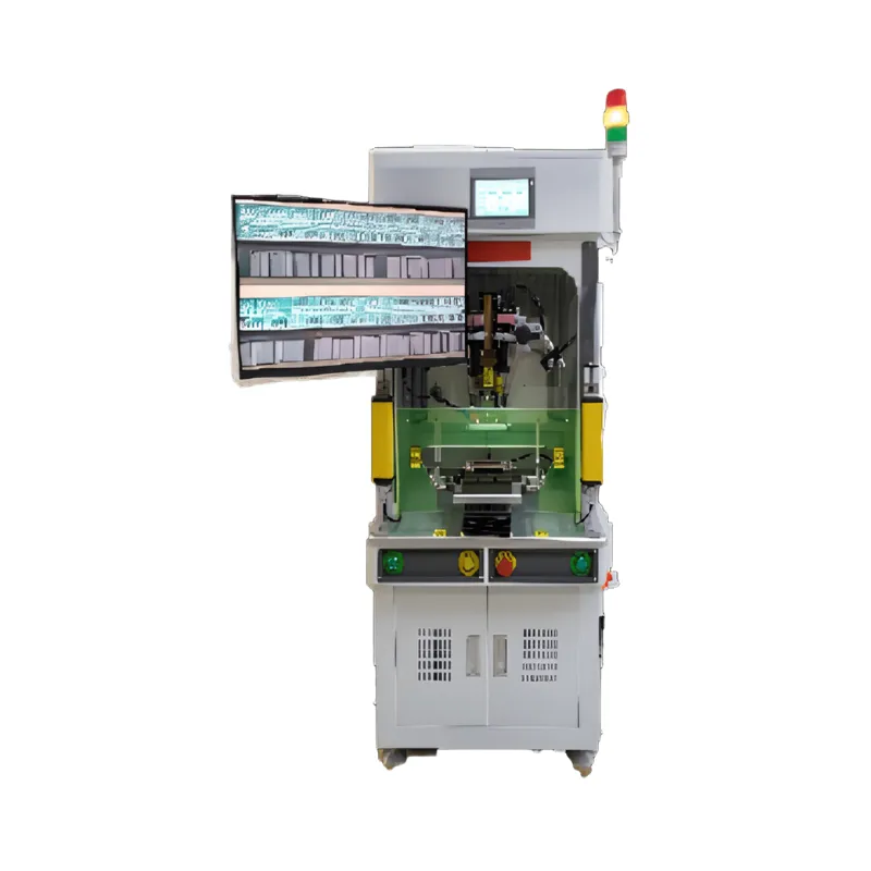
A vision inspection system for cable assembly is an automated quality-control setup that uses industrial cameras, controlled lighting, and image-processing software to examine cable assemblies during and after production. Instead of relying on an operator's eyes, the system captures images of the product at defined stations, compares them against acceptance criteria, and makes a pass/fail decision in real time.
In a cable assembly context, the system typically performs two complementary roles. The first is in-process guidance and monitoring: cameras watch critical steps such as stripping, forming, and connector insertion, and feed position data back to the control system so the machine can correct itself. The second is final inspection: after assembly and soldering are complete, the system verifies that the finished cable meets visual quality requirements before it is packed or released.
Because the inspection criteria are defined in software, every unit is judged by the same standard. This removes the variability that comes from shift changes, operator fatigue, and differing interpretations of what counts as a defect — which is precisely where most manual inspection systems break down.
Pain Points: Cable Defects Causing Data Center Downtime, High RMA Rates, and Manual Inspection Gaps
To understand why automated vision inspection has become a default requirement in high-speed cable production, it helps to look at the three problems that cable manufacturers run into most often.
Cable Defects That Cause Data Center Downtime
High-speed cables serve AI servers, data centers, and high-speed communication equipment, where a failed interconnect can bring down an entire link. Defects such as damaged insulation, exposed conductors, incomplete shielding, or a connector that is not fully seated may pass a quick visual glance but fail in the field under thermal cycling, vibration, or sustained data load. When that happens, the consequence is not just one bad cable — it is troubleshooting time, replacement logistics, and in the worst case, downtime attributed to the cable supplier.
High RMA Rates and the Cost of Escaped Defects
Every defect that escapes the factory becomes more expensive further down the chain. A defect caught at the assembly station costs seconds; the same defect found by the customer becomes an RMA: return shipping, root-cause analysis, rework or scrapping, and a mark against the supplier's quality record. For cable assemblers serving demanding customers, controlling RMA rates is therefore not a packaging afterthought — it starts with how reliably defects are detected inside the factory, before shipment.
Manual Inspection Gaps on High-Speed Cable Lines
Manual visual inspection struggles on modern cable lines for structural reasons. High-speed cable production runs at takt times that make it impossible for an operator to inspect every feature of every unit; the parts themselves are small, with fine-pitch conductors and miniature connectors that strain human eyesight; and judgment varies from person to person, so the same marginal unit may pass on one shift and fail on the next. The result is a gap: defects that a consistent, always-attentive system would catch slip through because human inspection was never designed for this volume, size, or repetition.
What Can Vision Inspection Detect in Cable Production?
The detectable defect list depends on where cameras are placed and what the process looks like, but on a typical automated high-speed cable line, vision inspection covers:
- Insulation and foil condition. Residual insulation or aluminum foil left after stripping, over-stripped or nicked insulation, and damage to the shielding layers.
- Conductor geometry. Conductor pre-forming and trimming quality, including length, shape, and exposure consistency after the strip-and-form steps.
- Connector assembly correctness. Connector orientation and polarity, wafer and housing seating, and whether sub-components such as shielding plates are present and correctly placed.
- Terminal and contact position. Terminal alignment inside the connector, verified through CCD vision checks similar to those used on automated assembly equipment.
- Solder joint appearance. The visual result of Hot Bar soldering — whether the joint looks complete and uniformly formed.
- Completeness and identification. Missing components, incorrect cable routing or cross-wiring, and the presence and readability of identification marks such as labels or codes.
The exact checklist is configured per product. A good system lets the manufacturer define which features matter for each cable family, so the same line can inspect different products simply by recalling a different recipe.
Vision Technologies for High-Speed Cable Lines
Cable assembly vision systems generally combine several building blocks. 2D vision handles presence/absence checks, position measurement, and surface appearance from a single viewpoint, and is well suited to verifying component placement, connector seating, and marking. 3D vision adds height and depth information, which matters when the inspection question involves coplanarity, insertion depth, or features that cannot be judged from one angle alone.
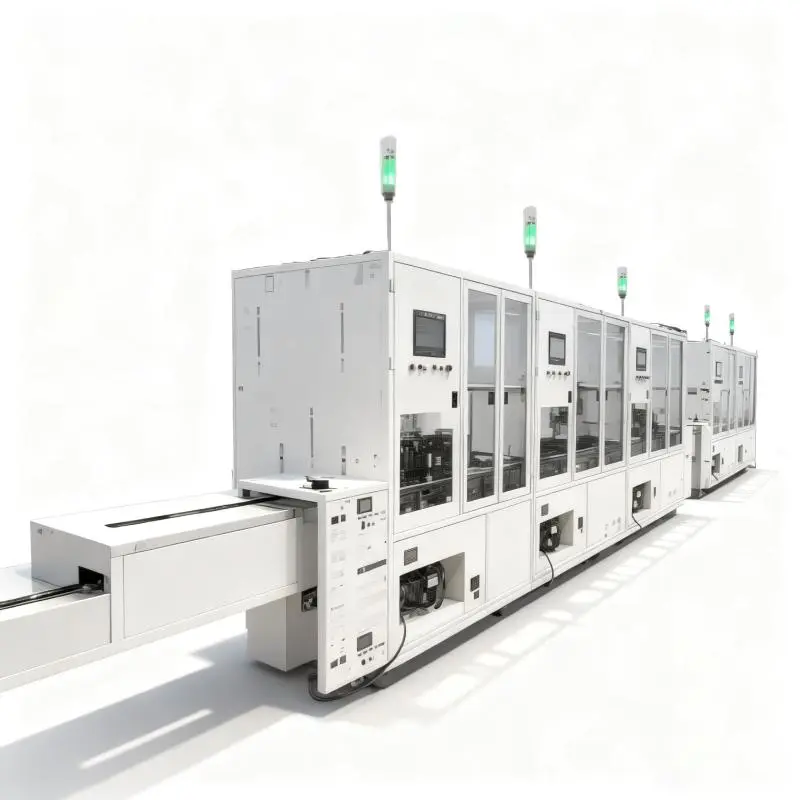
On high-speed cable lines, vision increasingly works together with the process rather than only after it. A representative example is Mijoint's fully automatic CDFP high-speed cable assembly line, which integrates the complete process chain — automatic wire feeding and cross-wiring, UV laser aluminum foil stripping and swinging, aluminum foil removal, CO2 laser insulation stripping, insulation removal, pre-forming and final trimming, Hot Bar soldering, and an automatic clamp and fixture reflow system — and uses high-precision servo systems together with vision guidance to guarantee assembly stability. In this architecture, vision is not a policeman at the end of the line; it is part of the control loop that keeps each station aligned, which is what allows the line to run with minimal redundant operator movement and truly data-driven production.
Lighting and fixturing deserve equal attention to cameras. Cables are reflective, cylindrical, and often glossy after stripping or soldering, so a system that works in the lab can fail on the line if the lighting dome, camera angle, and part clamping are not engineered for the actual product. This is one of the main reasons inspection capability is best evaluated as part of the complete automated line rather than as a standalone camera purchase.
Integrating Inspection with MCIO and CDFP Automated Lines
The most practical way to judge vision inspection for cable assembly is to look at how it fits into complete automated lines for the cable types that dominate AI-server and data-center interconnect.
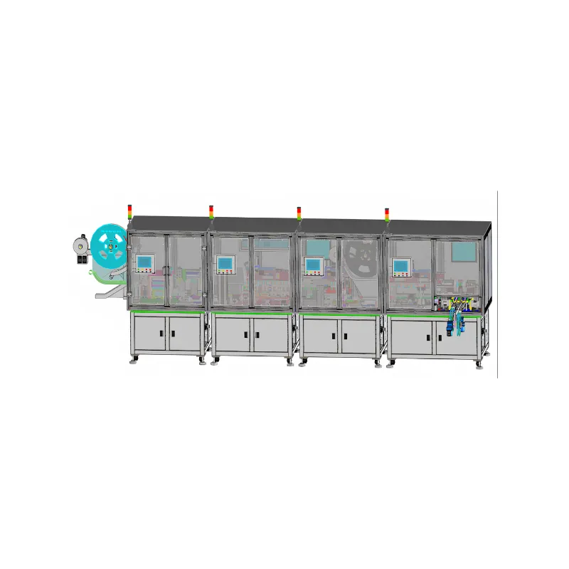
For MCIO cables, Mijoint's MCIO wire preparing automated line integrates the wire-preparing process chain — including UV laser stripping, aluminum foil swinging and removal, CO2 laser stripping, dielectric removal, and conductor pre-forming and final trimming, combined with automated Hot Bar soldering. The line is equipped with video monitoring and remote monitoring, records automatic production data traceability, and provides a standard data interface that can connect to a MES or to Mijoint's self-developed web platform. In other words, the inspection and monitoring layer is already part of the line's baseline design, not an add-on to be retrofitted.
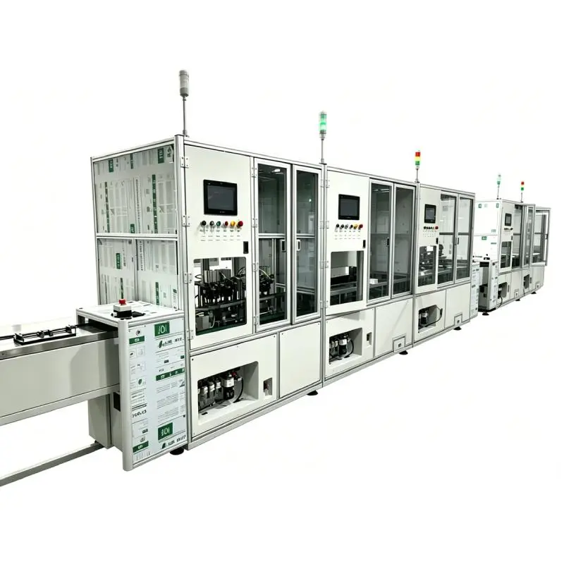
For CDFP cables, the CDFP wire preparing automated line covers the equivalent process chain and adds automatic soldering and an automatic clamp and fixture reflow system, in a line with an overall footprint of approximately L18350 × W1500 × H1950 mm. Like the MCIO line, it carries video monitoring, automatic production data traceability, and a standard data interface for MES integration. Stepping up a level, the fully automatic CDFP high-speed cable assembly line adds vision guidance across the whole process together with full MES integration, so assembly stability is supervised continuously rather than checked only at the end.
For high-speed connector and cable assembly beyond wire preparation, Mijoint's NearStack connector assembly line with inspection system is an integrated full-process intelligent line for NearStack series connectors and cable assemblies, covering wafer assembly, wire preparing, laser welding, shielding plate assembly, and automated unloading — engineered for AI servers, data centers, and high-speed communication equipment. Its built-in inspection system is what allows the line to hold high-speed, high-precision production across all of these processes without relying on downstream manual checks.
On the throughput side, these lines are engineered for real production volumes: the MCIO wire preparing line is designed for around 1,000 pieces per shift with an upgrade path toward 2,000 pieces per shift. Inspection and monitoring therefore have to keep pace with the line — another argument for integrated rather than bolted-on vision.
How Automated Inspection Reduces Cable Defect Rates and RMA
Automated vision inspection attacks the RMA problem at three points. First, it moves defect detection upstream: when vision is part of the process loop — as in vision-guided stripping, forming, and soldering — the machine corrects or flags a problem at the station where it occurs, instead of letting a defective unit continue downstream and consume more value before being rejected.
Second, it makes inspection consistent. Software-defined criteria mean the same defect is treated the same way on every unit, every shift. Marginal cases stop being a matter of whose eyes are on duty, and the defect data the system produces gives the quality team an objective basis for adjusting the process.
Third, it makes every unit traceable. When inspection and monitoring data are recorded automatically and passed to a MES through a standard interface, a field return can be traced back to its production data rather than investigated from memory. That shortens root-cause analysis, narrows any containment scope, and gives the customer evidence rather than assurances — which is often what determines whether a quality event becomes a routine RMA or a lost account.
How to Specify and Select a Vision System
When evaluating a vision inspection system for cable assembly, the following criteria separate systems that work in production from systems that only work in demonstrations:
- Start from your defect list. Specify the system against the actual defects your customers have returned or your audits have found — not against a generic brochure list. Each defect on the list should map to a camera position, lighting arrangement, and detection algorithm.
- Match optical capability to part geometry. Fine-pitch conductors, miniature connectors, and reflective surfaces determine the camera resolution, lens working distance, and lighting type you need. Ask for verification on your own parts, not sample parts.
- Check takt-time compatibility. The system must complete capture, processing, and decision within the line's cycle time. An inspection step that slows the line will be bypassed in practice, no matter how capable it is.
- Confirm data output. The system should export results automatically to your MES or quality platform through a standard data interface, so inspection results become traceability records rather than isolated images.
- Control false accepts and false rejects. Both matter: false accepts leak defects, while excessive false rejects flood the line with rework and erode operator trust in the system. Ask how the recipe is tuned and re-tuned as products change.
- Plan for changeovers. If you run multiple cable families, the system should switch between product recipes quickly — ideally with one-click recipe recall, consistent with how modern automated lines handle changeover.
Why Choose Mijoint's Cable Assembly Equipment
Mijoint builds vision, monitoring, and traceability into its cable automation equipment as an integrated design rather than an afterthought. The MCIO wire preparing automated line combines the full wire-preparing process chain with automated Hot Bar soldering, video monitoring, remote monitoring, automatic production data traceability, and a standard data interface for MES or Mijoint's self-developed web platform. The CDFP wire preparing automated line extends the same architecture with automatic soldering and an automatic clamp and fixture reflow system.
For full-process coverage, the fully automatic CDFP high-speed cable assembly line integrates vision guidance with high-precision servo systems across the entire process — from wire feeding and laser stripping through Hot Bar soldering and fixture reflow — together with full MES integration. For connector-level assembly, the NearStack connector assembly line with inspection system delivers wafer assembly, wire preparing, laser welding, shielding plate assembly, and automated unloading as one intelligent line for AI servers and data centers.
If your cable products or inspection requirements go beyond the standard configurations described here, contact our team to discuss a tailored automated line built around your products and quality criteria.
Conclusion
A vision inspection system for cable assembly is no longer an optional accessory for high-speed cable production — it is the mechanism that makes consistent quality possible at automated line speeds. By detecting stripping, forming, assembly, and soldering defects in-process, holding every unit to the same software-defined standard, and feeding inspection data into traceability and MES systems, it directly addresses the three problems that hurt cable suppliers most: field failures, RMA rates, and the inherent gaps of manual inspection.
The most reliable results come from inspection designed into the line itself — vision guidance working with servo systems, monitoring and data interfaces built into the equipment, and MES integration planned from the start. If you are evaluating a vision inspection solution for MCIO, CDFP, or other high-speed cable production, contact Mijoint's engineering team to request a customized equipment proposal, or visit the About Mijoint page to learn more about the company's cable automation capabilities.